

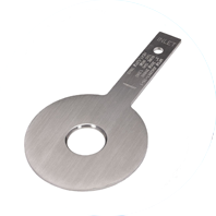
صفحه اریفیس ( Orifice Plate)
صفحه اریفیس ( Orifice Plate) طی بررسی های انجام شده توسط گروه فنی مهندسی فرآیند پردازان در مورد اندازه گیری دبی (جریان) مسیرهای آب ، بخار و گاز پیشنهاد ما با روش اندازه گیری صفحه اریفیس می باشد . روش های دیگر مثلا توربین میتر یا ورتکس به دلیل سرویس و تعمیرات سخت پیشنهاد نمی گردد .این سیستم در بسیاری از کارخانجات طراحی و اجرا شده است که در بخش پروژه های اجرا شده قابل مطالعه می باشد .
محاسبات طراحی صفحه اریفیس ( Orifice Plate) :
توسط نرم افزار Miller و Daniel انجام میگیرد و دیتاشیت های خروجی قابلیت اجرا و ساخت را دارا می باشند . (لینک دانلود نرم افزار سایزینگ Daniel)
۱-بهترین روش میترینگ طراحی و اجرای دبی سنج ( فلومیتر) با دقت بالا، صفحه اریفیس ( Orifice Plate) با در نظر گرفتن Compensator (جبران ساز تغییرات فشار و دمای خط) با خطای زیر ۱%
این آیتم به دو حالت قابل اجرا می باشد :
توسط فلوکامپیوتر که مقادیر اولیه دبی سیال مقدار فشار و دما اندازه گیری شده و مقدار دقیق محاسبه شده در خروجی فلوکامپیوتر ظاهر میگردد در این سیستم برای هر لوپ یک دستگاه فلوکامپیوتر مورد نیاز می باشد .
توسط PLC و کامپیوتر صنعتی : آنالیز مقادیر اولیه دبی ، فشار ، دما توسط PLC و کامپیوتر صنعتی انجام میگیرد . لازم به ذکر است کاتالوگ مربوط به فلو کامپیوتر را می توانید از بخش فلو کامپیوتر ها مطالعه و دانلود نمایید . این فلو کامپیوتر از دقت بسیار بالایی برخوردار میباشد به نحوی که خطای سیستم اندازه گیری به زیر ۱% میرسد.
تجهیزات مورد نیاز : در این روش، صفحه اریفیس ( Orifice Plate) ترانسمیتر اختلاف فشار، ترانسمیتر فشار و ترانسمیتر دما و همچنین فلوکامپیوتر مورد نیاز میباشد که در انتهای گزارش مشخصات فنی دقیق هر یک از تجهیزات ارائه میگردد . ترانسمیتر اختلاف فشار استفاده شده در این سیستم از برند معتبر امریکایی Rosemuont و یا آلمانی Endress Hauser که دارای خطای زیر ۰.۱ درصد می باشند .
۲-روش میترینگ اریفیس بدون در نظر گرفتن Compensator با خطای زیر ۵%
Orifice plate flowmeters
The orifice plate is one in a group known as head loss devices or differential pressure flowmeters.In simple terms the pipeline fluid is passed through a restriction, and the pressure differential is measured across that restriction. Based on the work of Daniel Bernoulli in 1738 (see Module 4.2),
the relationship between the velocity of fluid passing through the orifice is proportional to the square root of the pressure loss across it. Other flowmeters in the differential pressure group include venturis and nozzles.
With an orifice plate flowmeter, the restriction is in the form of a plate which has a hole concentric with the pipeline. This is referred to as the primary element.
To measure the differential pressure when the fluid is flowing, connections are made from the upstream and downstream pressure tappings, to a secondary device known as a DP (Differential Pressure) cell.
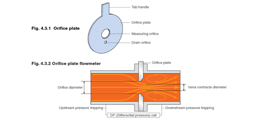
From the DP cell, the information may be fed to a simple flow indicator, or to a flow computer along with temperature and/or pressure data, which enables the system to compensate for changes in fluid density.
In horizontal lines carrying vapours, water (or condensate) can build up against the upstream face of the orifice. To prevent this, a drain hole may be drilled in the plate at the bottom of the pipe. Clearly, the effect of this must be taken into account when the orifice plate dimensions are determined.
Correct sizing and installation of orifice plates is absolutely essential, and is well documented in the International Standard ISO 5167.
Installation
A few of the most important points from ISO 5167 are discussed below:
Pressure tappings – Small bore pipes (referred to as impulse lines) connect the upstream and downstream pressure tappings of the orifice plate to a Differential Pressure or DP cell.
The positioning of the pressure tappings can be varied. The most common locations are:
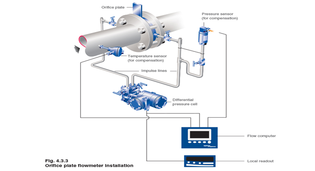
• From the flanges (or carrier) containing the orifice plate as shown in Figure 4.3.3. This is convenient, but care needs to be taken with tappings at the bottom of the pipe, because they may become clogged.
• One pipe diameter on the upstream side and 0.5 x pipe diameter on the downstream side. This is less convenient, but potentially more accurate as the differential pressure measured is at its greatest at the vena contracta, which occurs at this position.
Corner tappings – These are generally used on smaller orifice plates where space restrictions mean flanged tappings are difficult to manufacture. Usually on pipe diameters including or below DN50.
From the DP cell, the information may be fed to a flow indicator, or to a flow computer along with temperature and/or pressure data, to provide density compensation.
Pipework – There is a requirement for a minimum of five straight pipe diameters downstream of the orifice plate, to reduce the effects of disturbance caused by the pipework.
The amount of straight pipework required upstream of the orifice plate is, however, affected by a number of factors including:
• The ß ratio; this is the relationship between the orifice diameter and the pipe diameter (see Equation 4.3.1), and would typically be a value of 0.7.

شماتیک کامل روش اندازه گیری اختلاف فشار با استفاده از فلو کامپیوتر ( اعمال مقادیر فشار و دما در اندازه گیری فلوی سیال )
روش محاسبه مقادیر خطا و تاثیر فشار بر دانسیته سیالهای تراکم پذیر
Velocity flowmeters
The output signal from a vortex shedding flowmeter is a function of the velocity of flow only. It is independent of the density, pressure and temperature of the fluid that it is monitoring. Given the same flow velocity, the uncompensated output from a vortex shedding flowmeter is the same whether it is measuring 3 bar g steam, 17 bar g steam, or water or gas .
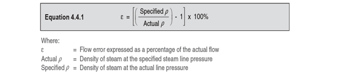
Flow errors, therefore are a function of the error in density and may be expressed as shown in Equation 4.4.1.
Example 4.4.1
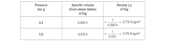
As a basis for the following examples, determine the density ( ) of dry saturated steam at 4.2 bar g and 5.0 bar g.
Example 4.4.2
A vortex shedding steam flowmeter specified to be used at 5 bar g is used at 4.2 bar g. Use Equation 4.4.1 and the data from Example 4.4.1 to determine the resulting error ( ε ).
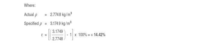
Therefore, the uncompensated vortex flowmeter will over read by 14.42%
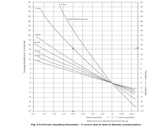
As one of the characteristics of saturated steam (particularly at low pressures up to about 6 bar g) is that the density varies greatly for a small change in pressure, density compensation is essential to ensure accurate readings.
Equation 4.4.1 may be used to generate a chart showing the expected error in flow for an error in pressure, as shown in Figure 4.4.6.
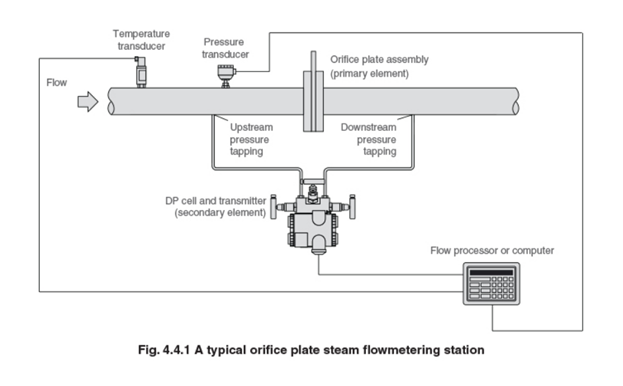
Differential pressure flowmeters
The output signal from an orifice plate and cell takes the form of a differential pressure signal. The measured mass flowrate is a function of the shape and size of the hole, the square root of the differential pressure and the square root of the density of the fluid. Given the same observed differential pressure across an orifice plate, the derived mass flowrate will vary with the square root of the density.
As for vortex flowmeters, running an orifice plate flowmeter at a pressure other than the specified pressure will give rise to errors.
The percentage error may be calculated using Equation 4.4.2.

Example 4.4.3.
An orifice plate steam flowmeter specified to be used at 5 bar g is used at 4.2 bar g. Use Equation 4.4.2 to determine the resulting percentage error ( ).
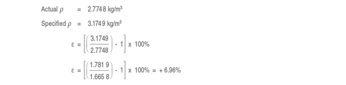
The positive error means the flowmeter is overreading, in this instance, for every 100 kg of steam passing through, the flowmeter registers 106.96 kg.
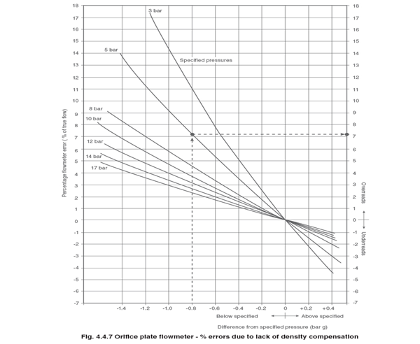
Equation 4.4.2 may be used to generate a chart showing the expected error in flow for an error in pressure, as shown in Figure 4.4.7.
When comparing Figure 4.4.6 with Figure 4.4.7, it can be seen that the % error due to lack of density compensation for the vortex flowmeter is approximately double the % error for the orifice plate flowmeter. Therefore, density compensation is essential if steam flow is to be measured accurately. If the steam flowmeter does not include an inbuilt density compensation feature then extra pressure and/or temperature sensors must be provided, linked back to the instrumentation system.
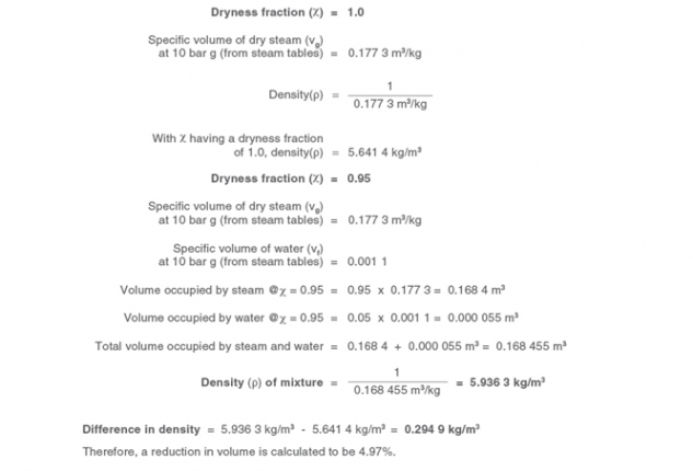
Dryness fraction variation
The density of a cubic metre of wet steam is higher than that of a cubic metre of dry steam. If the quality of steam is not taken into account as the steam passes through the flowmeter, then the indicated flowrate will be lower than the actual value.
Dryness fraction ( ) has already been discussed in Module 2.2, but to reiterate; dryness fraction is an expression of the proportions of saturated steam and saturated water. For example, a kilogram of steam with a dryness fraction of 0.95, contains 0.95 kilogram of steam and 0.05 kilogram of water.
Example 4.4.4
As a basis for the following examples, determine the density ( ) of dry saturated steam at 10 bar g with dryness fractions of 1.0 and 0.95.
مشخصات فنی تجهیزات مورد نیاز:
- صفحه اوریفیس بسته به سایز لوله و سایز طراحی .
- ترانسمیتر اختلاف فشار : DP Pressure Transmeter
مشخصات دقیق ترانسمیتر در کاتالوگ پیوستی میباشد که بر اساس محدوده کاری و رنج فشار قابل انتخاب میباشد.
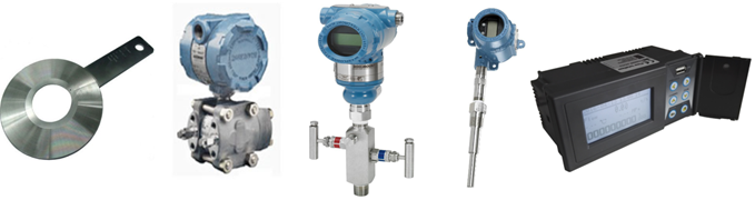
- ترانسمیتر فشار:
- ترانسمیتر دما :
- فلو کامپیوتر : Flow Computer
